Language


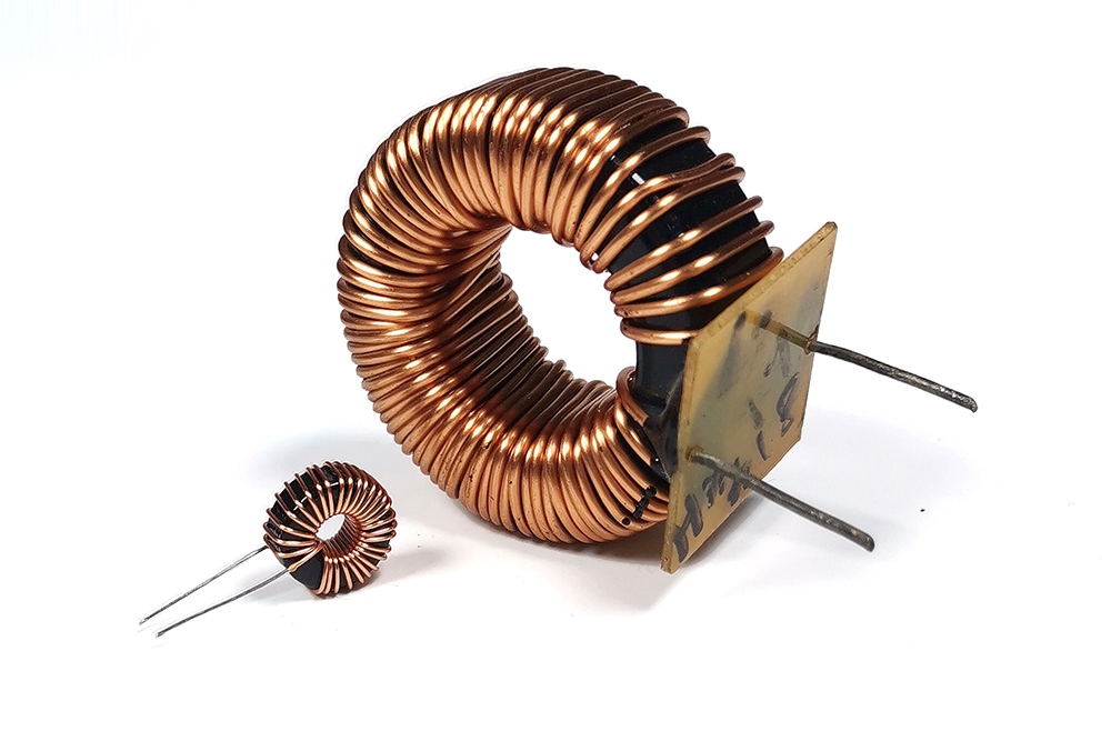
Guangdong Haoer Electronics Co., Ltd. and Foshan Pin'er Electronics Co., Ltd. are specialized manufacturers of precision inductors with extensive experience in design, production, and quality assurance. Over years of industrial practice, we have identified eight critical technical challenges that may compromise inductor performance, reliability, and application suitability. Below is a concise, technically grounded analysis of each issue---along with our validated mitigation strategies, implemented through rigorous material selection, process control, and comprehensive testing protocols.
1. Inter-turn short circuits
Caused by suboptimal winding techniques or inferior magnet wire quality, inter-turn shorts result in significant inductance deviation or functional failure. Mitigation: Implementation of standardized winding procedures and exclusive use of certified, pre-qualified magnet wire meeting IEC 60317 and UL 1446 specifications.
2. Inter-turn open circuits
Open circuits---often arising from mechanical wire breakage during winding or defective solder joints---are difficult to detect visually but lead to complete device failure. Mitigation: 100% automated optical inspection (AOI) of winding integrity and manual/automated electrical continuity verification for all solder connections.
3. Inadequate turn-to-turn insulation
Insufficient dielectric strength or inconsistent insulation coating thickness increases risk of both short and open circuits. Mitigation: Pre-production qualification and in-process monitoring of insulation materials---including dielectric withstand voltage testing per IEC 60243-1---and real-time coating thickness measurement.
4. Excessive inductance tolerance deviation
Deviations beyond specified tolerance bands typically stem from core material inconsistencies or winding parameter drift. Mitigation: Traceable sourcing of core materials with certified magnetic properties; closed-loop winding control systems calibrated to ±0.5% turn count accuracy; and 100% post-production LCR testing against customer-specified limits.
5. Poor temperature coefficient of inductance (TC-L)
Inductance variation under thermal stress restricts operational stability in temperature-sensitive applications. Mitigation: Selection of core materials (e.g., Ni-Zn ferrites, sendust, or controlled-permeability powdered irons) and structural designs validated for low TC-L (< ±50 ppm/°C) across the intended operating range.
6. Degraded high-frequency performance
At elevated frequencies, parasitic capacitance and core losses may induce inductance roll-off or self-resonance, leading to signal distortion or impedance mismatch. Mitigation: Frequency-targeted core material selection and optimized winding geometry (e.g., progressive layer winding, sectional winding, or litz wire configuration), validated via impedance analyzer characterization up to 1 GHz.
7. Premature magnetic core saturation
Saturation at nominal operating current causes abrupt inductance collapse and harmonic distortion. Mitigation: Core sizing and material selection based on worst-case DC bias and AC ripple current profiles; finite-element magnetic simulation (FEMM/MAXWELL) prior to prototyping; and DC bias testing per IEC 62029-1.
8. Susceptibility to external magnetic fields
Unshielded inductors may exhibit parameter drift or coupling-induced noise in magnetically noisy environments. Mitigation: Integrated magnetic shielding design (e.g., closed magnetic paths, mu-metal enclosures, or toroidal geometries); optional custom shielding solutions available upon electromagnetic compatibility (EMC) assessment.
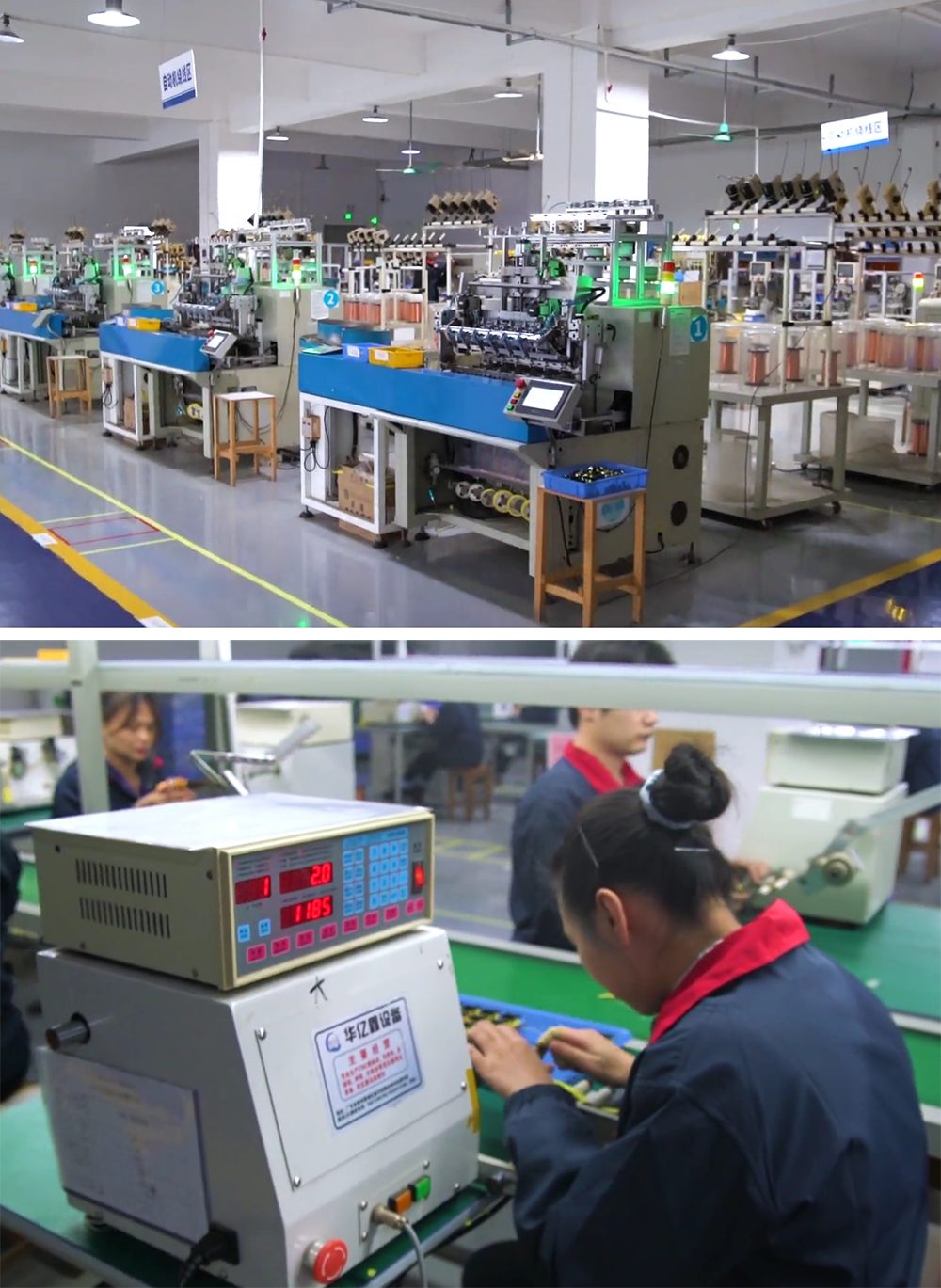
All eight challenges are systematically preventable through disciplined engineering practices---not reactive correction. Our integrated quality management system adheres to ISO 9001:2015 standards and encompasses three-tier verification: incoming material certification (including RoHS/REACH compliance), in-process parameter monitoring (SPC-controlled winding and soldering), and full electrical final test (L, Q, DCR, SRF, and DC bias). Furthermore, we adopt an application-driven co-engineering approach: collaborating closely with customers to define operational parameters---including frequency range, peak/rms current, ambient and self-heating profiles, and environmental constraints---to ensure optimal component specification, validation, and long-term field reliability.