
Language


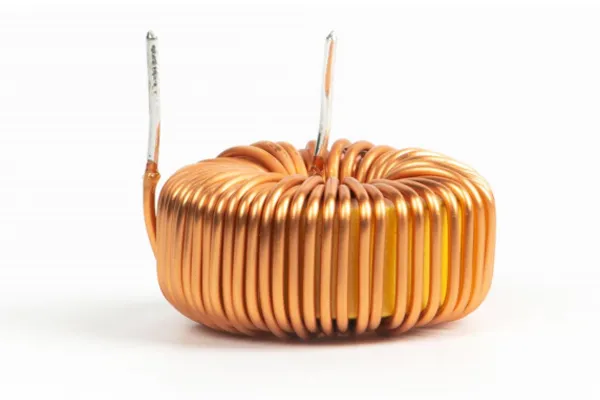
Despite its ring-sized appearance, a toroidal inductor plays a critical role in suppressing electromagnetic interference (EMI). Found on power cables, signal lines, and data buses, it acts as a silent filter: high-frequency noise is absorbed and dissipated as heat or magnetic energy, while the desired signal passes through undisturbed.
When high-frequency interference passes through a toroidal inductor, the inductor presents a sharp rise in impedance, effectively blocking the noise from reaching sensitive circuits. This is why toroids are commonly seen in power supply filters, USB cables, and display signal lines.
After rectification, a pulsating DC current flows through an inductor‑capacitor (LC) filter. The inductor stores energy during the switch on‑time and releases it during the off‑time, resulting in a smoother DC output and a stable operating environment for the load.
In a resonant tank circuit, a toroidal inductor combined with a capacitor acts like a band‑pass filter, allowing only a specific frequency to pass while rejecting others.
● Current capacity: Standard enameled copper wire works for most applications. For continuous temperatures above 85 °C, use Teflon or silicone‑insulated wire.
● Conductor type: Copper wire minimizes resistance; tinned copper wire improves solderability.
● Ferrite: Lightweight, good high‑frequency performance – suitable for medium‑frequency filtering.
● Iron‑silicon‑aluminum (Sendust) or iron powder cores: Higher permeability, resistant to saturation – preferred for high‑power PFC circuits and server power supplies.
● Rule of thumb: use ferrite for small signals, high‑permeability alloy cores for high currents.
● Close‑wound: Low distributed capacitance, suitable for resonant circuits.
● Spaced winding: Further reduces parasitic capacitance and raises the self‑resonant frequency.
● Tightly wound (concentric): Increases inductance by stacking layers.
● Honeycomb winding: Staggered layers reduce parasitic capacitance and improve self‑resonant frequency.
● Bifilar winding: Two wires are wound symmetrically in opposite directions – differential‑mode signals cancel, while common‑mode noise is attenuated.
● Crossed winding (≈90° angle): Cancels magnetic flux between the two windings, boosting common‑mode rejection. For high‑power applications, multiple parallel windings reduce skin effect and distribute heat evenly.
Traditional manual toroidal winding suffers from small aperture, high speed variation, and large tolerance. Modern fully automatic winding machines, combined with soldering and testing lines, achieve inductance repeatability within ±0.05%, even for wire as fine as 0.3 mm. Customers provide only three parameters – package size, current rating, and impedance – and samples are available within 48 hours, supporting small‑batch, fast‑delivery production.
● Incoming material: Ferrite cores, magnetic powder cores, and wire come from top‑tier suppliers, with batch‑specific RoHS and REACH reports.
● In‑process control: Each machine includes a data‑traceability system. Every inductor can be traced to its production time, operator, and test results.
● Final inspection: UL and CE certified. RoHS compliant by default. Non‑conforming parts are scrapped and traced back to the batch origin.
● Identify noise frequency: Use a spectrum analyzer to locate the interference peak, then select a core with appropriate impedance at that frequency.
● Allow current margin: Size the inductor for at least 1.5× the peak operating current to avoid core saturation.
● Maintain symmetry: Install common‑mode inductors symmetrically to ensure identical magnetic paths for both windings – this maximizes suppression performance.
From phone chargers to server power supplies, from automotive ADAS to industrial RS‑485 buses, toroidal inductors quietly ensure electromagnetic compatibility. By choosing the right materials, applying suitable winding methods, and leveraging automated production, you can turn a small toroidal core into a strategic component – keeping noise outside and letting signals flow freely.


